
During building my pedals, I decided to make my own pedal controller using cheep and affordable components. Already having some experience with Arduino boards, I know their capabilities and decided to route a STM32 way this time (mostly to learn something new though).
Here is the comparision of Arduino Leonardo (which is a most likely candidate for our goal) and STM32F103C8T6 (which I used)
| Arduino Leonardo | STM32F103C8T6 | |
|---|---|---|
| Flash | 32KB | 64KB |
| SRAM | 2.5KB | 20KB |
| EEPROM | 1KB | Absent |
| Architecture | 8-bit ATMEL AVR | 32-bit ARM CORTEX-M3 |
| Frequency | 16MHz | up to 72MHz |
| GPIO pins | 20 | 26 |
| PWM | 7 | 12 |
| Timers | 1x 16-bit, 2x 8-bit | 3x 16-bit, 1x pwm |
| Peripheral | 10-bit ADC (6 channels) 1x I2C 1x SPI 1x UART USB | 2 x 12-bit, 1 μs A/D converters (7 channels) 7-channel DMA controller 3x USART 2x I2C 2x SPI CAN USB |
As you can see, specs for stm32f103c8 are not so bad. And it’s cheaper than Leonardo!
One big drawback is that you need additional external programmer. But its not expensive also, total price for mini board + programmer is still comparable with Arduino clones.
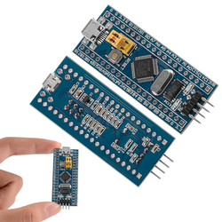

I bought both items on aliexpress.com, search for «STM32F103C8T6 Minimum System Development Board» and «ST-Link v2 mini», for example this and this. Also there is another version of the board called BlackPill — link. It has less available pins, but has mounting holes.
Schematics for the dev board:

Pinout in pdf — The-Generic-STM32F103-Pinout-Diagram
So, after some time, I programmed simracing-oriented firmware for the device.
Device capabilities are:
- Gamepad/Keyboard/Mouse emulation
- 6x 12-bit (4096 steps) axises
- rotary encoders support
- rotary switches support
- matrix buttons support
- single buttons support
- axes calibration, axes shaping
- analog inputs as buttons
- 1kHz exchange rate with PC, which means 1ms maximum latency for axes
It can be used for DIY buttons boxes, button rim plates, pedals, hand brakes, gear shifters, etc, etc — everywhere you need gamepad/keyboard/mouse interface with PC. Its usual HID device, no additional drivers installation needed.
Here is pinout you get after flashing the firmware first time:
             STM32F103C8T6
	   -------------------
	- |3VB		 +3.3V| -
  	- |C13		   GND| -
  COL1	- |C14		   +5V| -
  COL2	- |C15		    B9| - ROW6
  ADC0 	- |A0		    B8| - ROW5
  ADC1 	- |A1		    B7| - ROW4
  ADC2	- |A2		    B6| - ROW3
  ADC3	- |A3		    B5| - ROW2
  ADC4	- |A4		    B4| - ROW1
  ADC5	- |A5		    B3| - COL4
  ADC6	- |A6		   A15| - ROT11
  COL5	- |A7		   A12| -
  ROT1	- |B0		   A11| -
  ROT2	- |B1		   A10| - ROT8
  ROTA	- |B10		    A9| - ROT7
  ROTB	- |B11		    A8| - ROT6
	- |R		   B15| - ROT5
	- |+3.3V	   B14| - ROT4
	- |GND		   B13| - ROT3
	- |GND		   B12| - COL3
	   -------------------
Also I programmed small PC-based app named OSHStudio, which allows you to choose a function for each pin. Pins’ functions can be selected in the «Pins Configuration» tab, also here you can choose your board type. Here is how the initial pinout looks in OSHStudio, when you click «Get Config from Device»:

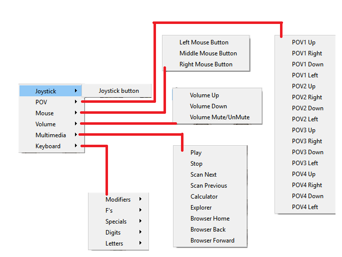
Mouse
You can configure analog input pin as 1 of 2 mouse axes or mouse’s wheel. Left/Middle/Right buttons can be configured on the Buttons Tab.

Buttons
When buttons wired in matrix, columns have to be connected to Button Matrix COLUMNS pins, rows — to Button Matrix ROWS pins. Single separate buttons (not matrix), can be connect to «Single Button +3,3V» or «Single Button GND». If you connect button to «Single Button +3.3V» than connect the other side of button to +3.3V, if you connect button to «Single Button GND» than connect it to GND. Here is an example of matrix wiring:

You can test your buttons in the «Buttons» tab of OSHStudio. Also you can choose «function» for each button — how it’ll be act at PC — as gamepad button, keyboard key, etc. All buttons are configured as gamepad button as default.

Rotary Encoders
The firmware supports full step, half step and quarter step encoders. Rotary encoders can be wired in «chained» or «single» configuration. Chained config means you wire side encoders’ pins (PINA & PINB) together and central pin become «control» pin. Central pin identified your encoder type — 1/1 (full step), 1/2 (half step) or 1/4 (quarter step). You can wire different type encoders in one chain.
Schematics:

Also encoders can be connected in single configuration. In this case you should configure side pins according to the type of encoder and central pin have to be connected to +3.3V.
Schematics:

If necessary you can remap encoders pins on the «Single Encoders Config» tab.

Encoders can also be tested in the «Buttons» tab.
Rotary Switches
Virtual button is «clicked» when shaft is changing position.

Axes
Analog pins ADC0 — ADC6 used to connect potentiometers or other analog inputs. Also you can calibrate axises in OSHStudio, and calibration values in this case will be stored in MCU itself. After calibration an axis is «expanded» by the controller, so PC always sees axis as 4096 steps. There is also a possibility of AutoCalibration of axes. Raw sensor value is shown as RED scale (there is no impact of calibration on it) and axis value is shown as GREEN scale (direct impact of calibration).

As you can see, there is also «Combined axis» function. It means you can combine 2 analog inputs in one axis. The function is mainly intended for rims with 2 clutch paddles. There are 2 possible modes:
- cooperative work — in this mode results from both analog inputs are summarized. You can choose weight of each input by slider.
- each on his own — each analog input works independently but for one axis. For example you can short calibrate an one input (paddle) for fast gear changes and an other calibrate as normal axis — for starting.
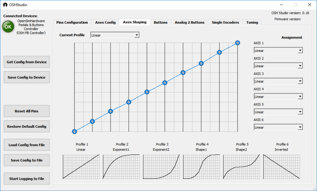
Also you can make axis shaping. There are 6 predefined shape presets and you can modify them as you want and give them its own name
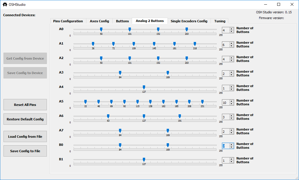
Analog2Button
Beginning with 0.15 version there is a more advanced possibility to map analog iinputs to buttons. You can configure up to 10 analog inputs and each of them can be mapped up to 10 buttons (keep in mind though total number of buttons is still 64). You can define it in the Analog2Buttons tab
Tuning Tab
You can tune such parameters as:
- «Your identifier for the device» — unique identifier for the board, if you have for example few boards, you can assign different idetigiers to them — «pedals», «buttonsbox», etc
- «USB polling interval» — means interval between USB packets, i.e. 1ms means 1kHz USB exchange frequency. For high performance devices you can try decrease this down to 1ms, for anything else default 16ms probably is enough.
- «Amount of time a button will be pressed when Rotary Encoder position changed» — virtual button will appear as pressed during this time, for encoders
- «Amount of time a button will be pressed when Rotary Switch position changed» -virtual button will appear as pressed during this time, for rotary switches
- «Amount of time a button will be pressed when Analog Input position changed» -virtual button will appear as pressed during this time, for analog2buttons inputs
- «Time since previous Rotary Switch change» — if you change rotary switch position in less time than the parameter then buttons presses will not be registered. So if you rotate switch fast enough then intermediate positions will not be registered.
- «Time since previous Analog Input position change» — same as previous one, but for Analog2Buttons types
- «Debounce time for Rotary Encoders» and «Debounce time for Buttons» — try to increase it if you have problem with phantom presses

Notes
I recommend set to «Not used» all unused pins 🙂
Source code in my github project.
Available firmware + OSHStudio app:
Version 0.16 — keyboard/mouse emulation, buttons functions, axes shaping
Version 0.15 — More stable USB operations, more advanced Analog2Buttons type
Version 0.14 — Autocalibration axes, Analog2Button pin type and combined axis added
Version 0.13 — Single Encoders Config tab added
Version 0.12 — Tuning tab added
Version 0.11 — Single encoders support added
If you wonder how to flash firmware to the board you can check this post — How to flash firmware to STM32Fx

Hi, could you give me a hint on how your app works? Im trying to develop my own controller and im wondering what would be the best option to change the config on the microcontroller through a PC software
НравитсяНравится
Hi,
I have do all steps and everything was working perfect. I have 14 Buttons in Matrix and 2 Rotary Encoders in Chain. All works perfect for 2 Days. On third Day some buttons stop working completely and the Encoders only works sometimes.
What is wrong here? Why they stop working?
НравитсяНравится
Don’t know when to update again
НравитсяНравится
Hi,
I tried to connect an encoder KY-040 to the board but it does not work.
Is it possible to connect such an encoder? If not, do you have an example
which one will work?
Regards,+
Kai
НравитсяНравится
Support for a «funky switch» (ALPS — RKJXT1F42001) would be awesome. The issue is always the ‘PUSH’ function which triggers with a direction input. Most software won’t isolate the ‘PUSH’ function.
Normally I just wire the ‘Directional inputs’ and the ‘Encoder inputs’ and not the ‘PUSH’ to avoid errors.
НравитсяНравится
Good day, after changing the pins on OSH — should windows see something different in usb controllers? ive changed so many things and windows always only says 6 axis, 32 buttons and hat.
also with v0.16 when selecting analog2button, OSH crashes and doesnt save config,
all others work,
had to go back to v0.15 to get that loaded but still windows doesnt see the changes i made.
i am looking to use rotary switches.
Thanks
НравитсяНравится
Hello, wanted to ask if there will be any feedback system version coming anytime soon.
НравитсяНравится
If you want an FFB controller, look at EMCDevelopment on Facebook.
НравитсяНравится
I can’t seem to get any rotary encoders to work — any tips? I’ve wired them exactly like the diagram. CTS 288 models, which i’ve used with other stuff in the past without issue. Button matrix, rotary switches all work great otherwise.
НравитсяНравится
Hello friend, were you able to solve your problem ?? The same thing happens to me, I want to update my arduino simulation pedals to stm32, connect everything as it should be but does not recognize any axis, as if they had no signal, does nothing, I am worried because I already disassemble all my arduino electronics.
НравитсяНравится
Hi, i’m trying to build an hydraulic pedals set for a driving simulation
I bough 2 Hall sensor (A1302) for clutch/gaz and an oil pressure sensor for brake.
But i think i dind’t pick the right parts, both Hall sensor and pressure transducer has an operating voltage range from 4.5V to 6V but STM32 datasheet say «ADC 0-9» are «not 5V tolerant»
I have 2 questions :
— Will i fry my board if i conect these parts on 5V?
— If i buy new 3.3V transducer and Hall sensor (like Honeywell SS49E), they all seems to have very tiny output voltage range, going from 1.8V to 2.2V, should i use an amplifier board and convert the signal from 0V to 3V to get a better resolution or it’s ok i will still be able to use the 4096 steps?
Thanks a lot for sharing your amazing work, without you i wouldn’t even imagine use such pedals set and now the dream is coming true, THX !!!
НравитсяНравится
I use this with those sensors (hall and pressure transducer) at 3v and it works perfectly fine. They are rated at 5v but just use 3v. DO NOT use 5v or it will blow the AD converter on that pin.
НравитсяНравится
Hello friend, were you able to solve your problem ?? The same thing happens to me, I want to update my arduino simulation pedals to stm32, connect everything as it should be but does not recognize any axis, as if they had no signal, does nothing, I am worried because I already disassemble all my arduino electronics.
НравитсяНравится
Congratulations for making the software free .. I made myself a pcb to be able to use your software and everything is ok! I consult you, you can share the source code of the software with me since in github I only found the v16 version and I need v15.
Thank you.
НравитсяНравится
Hello, greetings from Argentina. Works with load cell and amplifier HX711??
НравитсяНравится
Hello,
Is it possible to add in the «combined axis» a option to change the cooperative work % with a additional axis or encoder?
Is it also possible to add LED support? For a RPM or when you press a button that the LED stays on for an x amount of time?
НравитсяНравится
Hello. I’m really excited about the features that are possible here. Great job!!!
Is it not yet possible to operate the Alps 7 way switch correctly? I read in a German forum that it is possible with a resistance. But I don’t know what to do. Thank you
НравитсяНравится
I just finisht my first wheel using the SMT32 blue board. Had some issues long the way, which all could be solved but there was one that kept me very busy.
That was the fact that all hardware attache to the board (buttons, rtary and potentiometers) stopt working for 2 or 3 seconds.
In those seconds nothing reacts. Can tell you, is not fun when you want to downshift for a corner and nothing reacts.
Tried several things long the way. New USB cables, other USB ports, updating windows, resolder all hardware. Nothing did help.
Even tried other SMT32 board (a total of 3) and all gave me the same issue.
Starneg this was that when board stopped reacting, Windows (11) did not give me any sound of USB removal . So windows kept seeing the board.
And this was also visible when using the wheel and havong the game controller windown in fron. OSH bord had an OK , even when buttons stopt reacting.
So next thing I tried was downgrading the FW to 0.15 Fix…and gues what… Hardware reacts as it should. Teste the wheel for at least 15 min, and not once I had a not recting hardware.
So i am sure that the problems is on FW 0.16
Shame because I find FW 0.16 better for my dual clutch pedal. Somehow is works better then FW 0.15
I really hoep you can look at the firmware and see if you find something wrong with it. And maybe make a fix for this issue.
For the rest…its a great piece of software. Thanks for that
НравитсяНравится
Can you share you wiring and setup for the potentiometers please. Im having trouble with all 3 firmwares. Cant see any movement from potentiometers at all?
НравитсяНравится
Hi there, im stuck with this software. no matter which firmware i try 0.14, 0.15 or 0.16 i am unable to see any axis movement in the Axis Configuration tab. Please help
НравитсяНравится
Measuring the voltage on the output of the potentiometer i am seeing between 0 — 3.3v but not registering in OSHStudio on any version of firmware?
НравитсяНравится
Hi Craig,
Which pins are you using for the potentiometres? which potentiometers are you using?
I have one potentiometers 10k in A0 and the other in A1 and both works fine.
I have troubles with cooperative mode in v0.15 though.
Regards
Alex
НравитсяНравится
Hi Alex, thanks for your reply. I have tried a number of brands and types of potentiometers and typically 5k or 10k. I have tried configuring on A0, A1, A2, A3, A4, A5, A6 with no joy. I have also tried numerous STM32F103 boards with V0.14, V0.15 and V0.16.
Im in a bit of a pickle as i have managed to build my wheel around the STM32F103 board and have managed to get my encoders and buttons all working. Just need the «pots» for my clutches.
I suspect over here in little old New Zealand that we are seeing pretty much all fake boards so wondering if im fighting a loosing battle.
Would be awesome if this was available for other sorts of boards.
Regards
Craig
НравитсяНравится
Hello friend, were you able to solve your problem ?? The same thing happens to me, I want to update my arduino simulation pedals to stm32, connect everything as it should be but does not recognize any axis, as if they had no signal, does nothing, I am worried because I already disassemble all my arduino electronics.
НравитсяНравится 1 человек
Hey Craig,
have you solved the problem with the pots? It looks like, that I have the same problem.
I have tried now 3 different BluePill Boards, a lot of different pins and also several potentiometers and no chance to get a signal from my axes. Buttons are no problem.
I’m starting to think I’m stupid because I built a joystick with a buddy a year or two ago.
Regards,
Markus
НравитсяНравится
Hi Markus, unfortunately i have had no joy. I have now tried 10 different STM’s from different providers all with the same fault (no analog) Even had a kind gesture from another user here who purchased some STM’s in his country only to find they were fakes as well.
НравитсяНравится